5 COMMON INSTRUMENTATION FAILURES — AND HOW TO PREVENT THEM
Discover the top 5 instrumentation failures in industrial automation and how to prevent them with smart diagnostics, maintenance, and system design tips.

INTRODUCTION
Reliable instrumentation is essential for safe and efficient industrial operations. Yet, failures can and do happen. This post dives into five frequent instrumentation failure modes and shares practical, preventive strategies to keep your systems running smoothly.
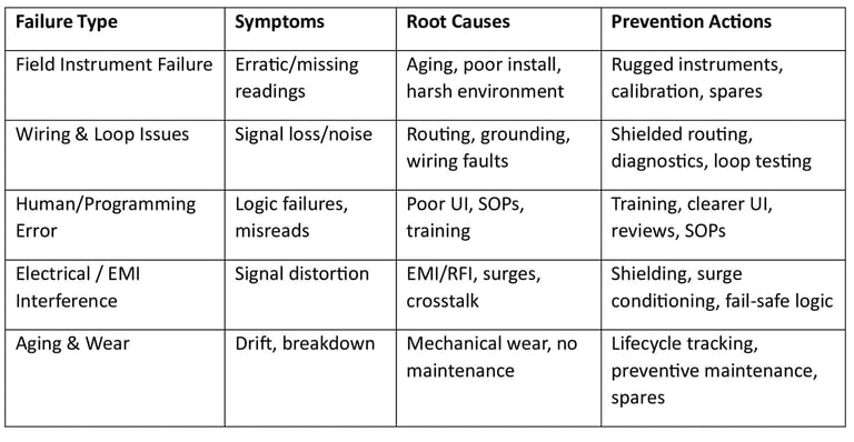
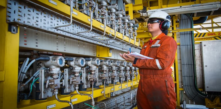
1. FIELD INSTRUMENT FAILURES (SENSORS, VALVES, TRANSMITTERS)
Problem: Erratic or no readings, stuck valves, or loss of control due to mechanical wear, environmental exposure, or calibration drift.
Why It Happens: Aging parts, incorrect installation, and harsh ambient conditions.
Fix It:
Choose rugged, environment-fit instruments (e.g., insulation for capillary tubes, proper mounting).
Schedule calibration and inspections.
Stock and swap out components proactively.
2. SIGNAL WIRING & LOOP PROBLEMS
Problem: Irregular readings, flatlining, or noise due to poor wiring or loop issues.
Sources: Electrical noise, poor grounding, miswiring, degraded connections.
Preventive Measures:
Use shielded cables, adhere to grounding standards.
Route signal lines away from EMI sources.
Employ proper wiring protocols and regular diagnostics.
Visual Aid: Use the Loop Diagram to visualize wiring components and trace fault paths .
3. HUMAN ERROR & PROGRAMMING MISTAKES
Problem: Incorrect sensor readings or actions because of operator or programmer mistakes.
Why It Happens: Poor training, confusing HMIs, buggy PLC logic, or poor SOPs.
Regularly train operators and engineers.
Simplify UI/SCADA workflows.
Implement peer reviews and structured programming practices.
Use standardized checklists and SOP documentation.
4. ELECTRICAL & ENVIRONMENTAL INTERFERENCE
Problem: Signal inaccuracies due to EMI/RFI, transient surges, or grounding issues.
Prevention:
Deploy surge protectors and signal conditioners.
Separate high-voltage and signal vessel cabling.
Validate isolation and grounding integrity.
Consider fail-safe circuit design when safety-critical.
Visual Aid: The Fail‑Safe Logic Diagram illustrates how wiring can be designed so a failure triggers a safe shutdown .
5. AGE-RELATED DEGRADATION & HARDWARE WEAR
Problem: Gradual failure or drift of sensors due to aging and lack of maintenance.
Why It Happens: Wear, corrosion, or outdated components without replacement How to Prevent:
Implement preventive maintenance schedules.
Log component lifespan and replace per lifecycle expectations.
Keep critical spares readily available.
VISUALIZING ROOT CAUSE — FAULT TREE ANALYSIS
Use the FTA diagram—like the one shown above—to break down failure sources using logic gates. It’s especially handy for complex systems where a failure can have multiple contributing factors .
SUMMERY