HOW TO CALIBRATE A PRESSURE TRANSMITTER IN THE FIELD – STEP-BY-STEP GUIDE
Accurate pressure transmitter calibration ensures precise measurement and reliable process control. This blog walks you through a detailed information for field calibration, complete with visual aids and expert-backed steps.
INTRODUCTION
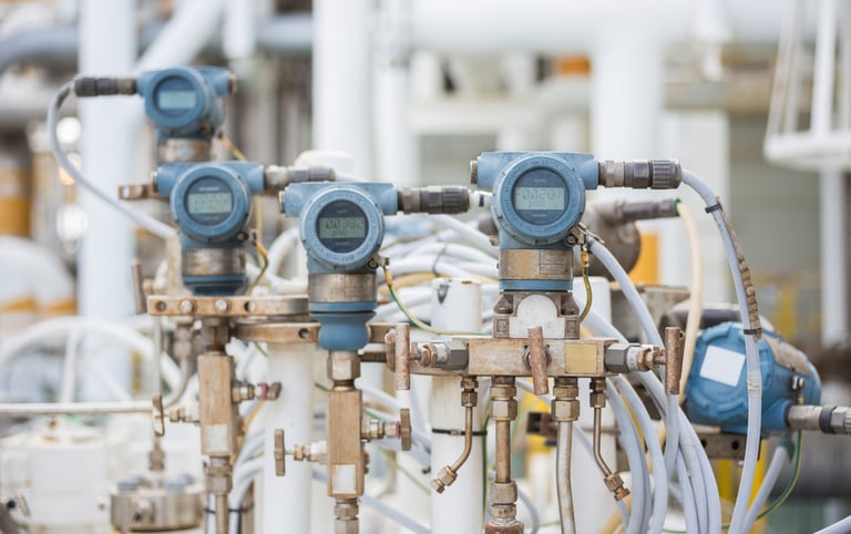
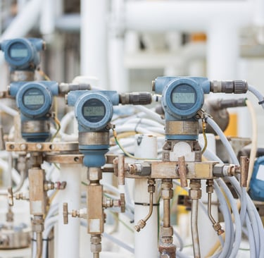
A pressure transmitter is an essential device used in industrial processes to measure the pressure of gases or liquids and convert that measurement into a standardized electrical signal (typically 4–20 mA or digital protocols like HART, Profibus, or Modbus).
BASIC PRINCIPLE & OPERATION
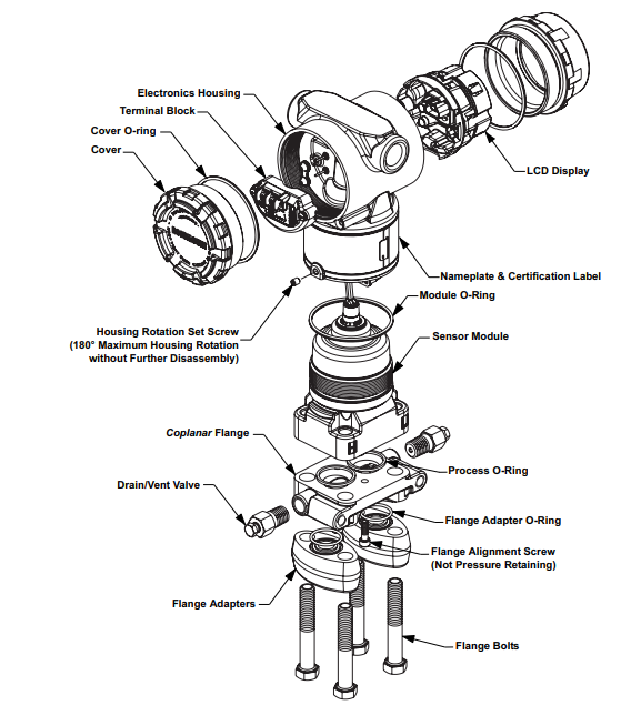
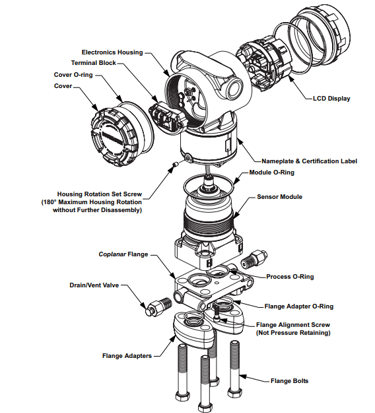
At its core, a pressure transmitter works by:
Sensing pressure via a mechanical component (usually a diaphragm).
That diaphragm deforms slightly under pressure.
The deformation is detected by a sensor element like a strain gauge, capacitive sensor, or piezoelectric crystal.
The mechanical movement is converted to an electrical signal, then conditioned and transmitted as an analog or digital output.
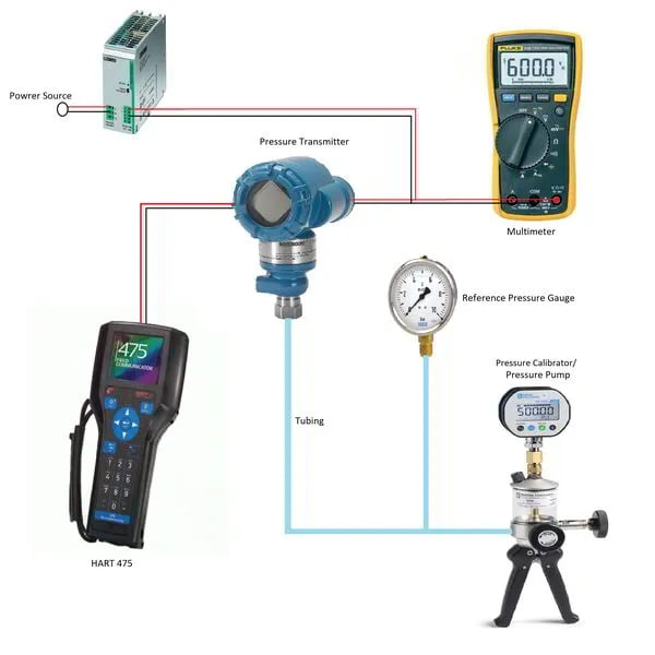
REQUIRED TOOLS & EQUIPMENT
Hand-held pressure pump or calibrator (hydraulic for high pressure, pneumatic for low)
Reference pressure gauge (preferably 1.5× the range of the transmitter)
Digital multimeter (for reading 4–20 mA loops)
HART communicator (for smart transmitters)
24 V DC power supply (if not loop-powered)
Appropriate fittings and tubing that match transmitter connections
STEP-BY-STEP FIELD CALIBRATION PROCEDURE
1. Safety First & Isolate the Transmitter
Secure necessary work permits. Conduct toolbox talk and wear PPE.
Switch control valves to manual mode or bypass interlocks. Activate Maintenance Override (MOS).
Close process isolation valves and vent or bleed the transmitter to relieve any residual pressure.
2. Prepare the Setup
Connect a hand pump or pressure calibrator to the transmitter’s pressure port with leak-proof fittings.
Wire the multimeter in series with the 4–20 mA loop or connect a HART communicator as needed.
Ensure setup stability—free from vibration and electrical noise.
Preload the sensor by applying ~90% of range (for better linearity), holding for ~30 s, then releasing.
3. Conduct Zero & Span Checks
Apply 0% pressure (atmospheric or vacuum for absolute transmitters). Confirm a 4 mA reading. Use zero trim if needed.
Apply 100% pressure (full scale). Confirm a 20 mA reading. Adjust span using span trim as required.
4. Perform Multi-Point Linearity Tests
Apply pressure in increments (0%, 25%, 50%, 75%, 100%).
At each point, allow stabilization (~30 s) and note the mA output.
Repeat in reverse to check for hysteresis and linearity.
5. Evaluate and Adjust
Calculate % error:
% Error = [(Measured Output – Expected Output) / Span] × 100
``` :contentReference[oaicite:18]{index=18}
If within tolerance, skip further adjustment. Otherwise, repeat zero/span trims using HART or onboard potentiometers.
6. Finalize and Restore System
Record both "as-found" and "as-left" data (pressure vs. output) in a calibration report. Include device info, date, technician, equipment references, and traceability.
Close bleed/vent valves, disconnect all tools, and re-establish normal operation by opening isolation valves slowly.
Affix a calibration sticker (date, due date, initials) and verify transmitter returns to proper function.
TIPS & BEST PRACTICES
Keep reference equipment at least 3–4× more accurate than the transmitter.
Reduce calibration intervals for transmitters with diaphragm seals or exposed to harsh conditions.
Avoid frequent sensor trims unless necessary—factory calibrations are more precise.
CONCLUSION
Field calibration of pressure transmitters requires meticulous preparation, accurate equipment, and adherence to a systematic process. By following the steps outlined above, you ensure accuracy, repeatability, and regulatory compliance—all essential for reliable instrumentation performance.